Friday, September 21, 2012

Assembling the Base

To finish the hardware end of the project, the base assembly needed to be made durable enough to hold up to the inevitable tugs on the display cable and, as it turned out, gravity. Aesthetics were less important for the base than the display since it would be in the background when using the reader. At the same time, I'd see the base at least when turning the reader on, so I didn't want it to look too shoddy. 

The size of the parallel port I chose to use in my adapter to connect the display cable to the base made it impossible to enclose it within the base housing. I had considered using the laptop's built-in parallel port but dismissed the idea since making the necessary connections would have been hellish. Instead, I decided to run the adapter's wiring along the top of the base and have the parallel port jut out from the back of the base. That way, the keyboard would still be usable if necessary, and the base with the cable connected would remain fairly thin compared to having the port jut upward.

The adapter, completed
The first step was to finish the adapter a bit to fit the base. With a top plastic piece removed that covered the display socket removed from the base, there was a depression or groove along the base's top edge. I bent the adapter around so the wiring would fit more-or-less within the groove when plugged into the socket and so the parallel port pointed toward the back of the base. Then, I finished the adapter by wrapping the wires with electrical tape to form them into a short and fairly rigid cable.

With the adapter plugged into the socket, the added wiring prevented the plastic piece from being replaced on the base giving it a pretty unfinished look. So I cut a chunk out of the plastic piece to allow it to be attached to the base with the wiring extending through it. The adapter's short cable then ran along the top of the plastic piece to the parallel port instead of resting in the groove.

The adapter still needed something to hold it in place. The hinge covers were left over from having removed the display from the base. By screwing these to the plastic piece with a few small wood screws, I managed to repurpose the hinge covers to both hold the adapter in place and cover the tape-constructed adapter cable. As an added aesthetic bonus, the hinge covers' plastic matched that of the base housing. All in all, I thought the result didn't look half bad.

If only that had been enough. Unfortunately, the combined weight of the parallel port and the connector at the base end of the parallel cable leading to the display created a torque around the edge of the base sufficient to lift and pop off the plastic piece intended to hold the adapter in place.

After thrashing around a while thinking about the problem, I concluded that the easiest solution would be to add some type of rigid shelf to hold the port up. I had some scrap sheet metal that could be used but didn't want to deal with measuring it and cutting it and smoothing the edges at that point. Then I remembered a metal plate left over from a past dissection of a trusted college companion, my old Sharp scientific calculator. Digging the plate out of a closet, I attached it to the base, and - voila! - I had a shelf for the port. A little Velcro helped to keep the port in place on the shelf and, lacking the screw connections on the port housing, to hold the connected cable to the port.

But that still wasn't good enough for me. No, I later decided that the base just had to rest leaning against a wall on its right side. That caused gravity to pull the at the port toward the right side in the picture above, along the surface of the shelf. It eventually got to be too much for the Velcro, at which point I used some wire to lash the port to the shelf so it couldn't move in any direction. Fortunately, the metal plate had holes conveniently available to be used for the purpose.

The end product was a little less than perfect, but that's okay because... It worked!

And that's it for the hardware modifications! Well, almost... After all was said and done, I made one last alteration in the interest of environmentalism, which I'll discuss at a later date.

Still to come... The software side of things...

Sunday, June 24, 2012

Reader Control

There was, of course, the problem of control. A touchscreen display would've been great, but the laptop wasn't that advanced.

As you probably noticed from the Introduction, a touchpad was the chosen controller. Several pointing and control devices had been considered in addition to a touchpad, including some sort of keypad, a set of scroll wheels, a pointing stick, and a trackball. The touchpad won out based on flexibility and ease of integration with the display. A different choice may work better for you.

A pointing stick was high on the list based on size. It'd be smaller than about anything, but I couldn't find one that could be plugged in and used like a mouse. It would have had to be integrated into the display or some housing would have had to have been contrived, and arrangements would have been needed to wire it into the mouse interface on the base. On the other hand, USB and PS/2 touchpads were readily available and one could be attached to an edge of the display housing. That left the problem of figuring out a good way to attach it.

The Velcro came from a local fabric store. A nice older lady there asked what I was making with it, to which I smiled and said, “A computer.” She responded with silence and strange look...
In the end, I chose Velcro. Permanent attachment to the housing would have been easy enough, but temporary attachment would permit moving the pad to various locations as desired. Black-colored, soft, loop Velcro was attached around the three flat sides of the display frame and the matching rough, hook Velcro was attached on the back of the touchpad. The result provided a highly flexible solution with a fairly clean look.

I figured that, if something better came along, the touchpad could easily be replaced with a different controller of comparable size that could be plugged into an available USB or PS/2 port. But later in the project the touchpad turned out to be a very good choice with a few unanticipated advantages over other controllers.

Saturday, June 23, 2012

Assembling the Display

With the proof-of-concept trial done, it was now necessary to make things durable enough to be usable and finished enough to not distract from reading. Between the base and the display, the display was the more important in this respect since it would be the more jostled and bumped around of the two and would be the one that I'd be spending time looking at.

Different displays with different available space, materials, wiring location, and etc. will require different solutions to this problem.  Depending on your situation, you may need to be pretty clever and crafty to come up with a workable arrangement.  In my case, it took a bit of rigging to get things to work out...

The size of the display connector and the space in the display housing had already been considered.  I was sure the connector could be made to fit one way or another.  So, the first step was to cut an opening through which it would extend. This I accomplished by carving out parts of the top and bottom of the housing with a Dremel.

The intent was to bolt the connector directly to the housing, but was a bit of a tight squeeze and it turned out that there wouldn't be a way to do it securely. To get around those problems, I cut a metal picture hanger* in half and bolted each half to one side of the connector to form mounting extensions. Then I used the Dremel to cut the housing in places to fit the extensions as solidly as possible. Finally, I was able to fit the housing together and had a fairly decent connector added to the display.

Unfortunately, several of the wires were ripped out of their fragile connections in the process of fitting the connector. After a lot of tedious resoldering, the display was reassembled and tested. It worked pretty well at first. But the connector was a bit loose, and I found it possible to wiggle it enough to short something and cause the computer to reboot.

Reopening the display, I wedged a couple of small nuts between the housing and extensions, and then applied cyanoacrylate adhesive (i.e. “super glue”) to hold things in place. I also applied some of the glue to the connector extension nut/bolt connections to keep them from loosening.

The display was again reassembled and tested after everything had dried. Finally, I had a good, solid connector that was rugged enough for normal use and didn't seem to look too bad.

* If you're going to mod stuff, it helps to have a lot of junk lying around. :)

Friday, May 4, 2012

Connection to the Base

So, a base connection was needed to enable a proof-of-concept test. A parallel port connector just needed to be connected to the display plug. The result would essentially form an adapter that could be plugged into the existing socket on the base.

Before continuing, I have to point out in my defense that while I've had formal education in electrical theory, I've never had formal training in actually constructing circuitry. This has occasionally lead to less-than-wise decisions, one of which having been how to connect the plug to the connector.

Don't do this...
The obvious connection of lead wires to the connector was straightforward. After that, for some reason, I thought it would be best to attach wires from each of the plug and the connector to an intervening circuit board. Appropriate wires from each were to be soldered in different holes connected by prefab traces on the board. This turned out to be much harder than originally anticipated. The plug wires were so small compared to the hole size so that it took a lot of solder to hold them in place. Also, the hole spacing was such that it was difficult to keep all of that solder from shorting with an adjacent set. I don't think I made it farther than connecting two sets of wires before sitting back to think things through a bit more.

Searching for information on splicing wires, I ran across an excellent illustrated primer on splicing wires by "butt soldering". As it says, "This connection is physically and electrically sound while being cheap as well." I followed this guide and easily made all of the necessary connections to finish the protoadapter.

Having both connections to display and base, it was time for the moment of truth... Would additional circuitry be needed? I hooked up the six-foot cable, plugged the power brick into the base, and turned it on...

Oooo, the suspense is killing ya, isn't it...

Click to see the test result...
click browser back button to return

Wednesday, April 25, 2012

Connection to the Display

Next was to decide how to make the wired connections from the base to the display. I wanted to avoid hardwiring if possible to facilitate transport if needed, and it was clear from the service manual that the base and display were joined by a plug and socket connection. While the part numbers naturally weren't identified, I had the urge to make a cable that could be directly joined with the existing connectors. That would require tracking down the correct connectors.

I carefully examined the connectors after detaching the display from the base, which went fairly smoothly according to the directions in the service manual. Digging through part sites while paying particular attention to connector shapes finally turned up the necessary parts: SHD Connectors manufactured by JST. The parts were easily verified by comparing various dimensional measurements of the parts on the laptop to the part dimensions noted on the parts' spec sheets.

With the parts found, it turned out that a specialized hand tool was needed to properly make the electrical connections to the plug... And it cost, like, $1000! As that was just a bit outside my budget, I considered making the needed crimp connections using a pair of really small needle nose pliers. But that'd be a pain. And who wants to take on that level of tedium?

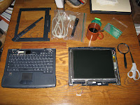
Display and base detached, display disassembled, and plug cut off from display.The connection was wired rather than being a flexible plastic circuit, so the decision was finally made to just wire in some other readily available connectors and use a readily available cable. The number of wires in the connection, the available space in the laptop display, and the stack of unused cables in my junk closet led to the choice... Parallel printer connectors. I cut off the plug from the display and was ready to go. 

Yes, it's backward.
Since a number of the wires were in twisted pairs, it seemed prudent to to use associated lines in the cable, if possible. Some searching turned up a table with complete parallel port cable pin assignments (see pp.9-10) and a connector pinout diagram with numbers adjacent pins for easy reference. Selecting one of the pins associated with a different signal ground pin for each of the twisted pairs and other pins for the remaining individual wires, the pinout was marked up according to the wire colors.

Then I noticed my mistake... The connections needed to be made to the female connector rather than to the male connector shown in the pinout diagram. Fortunately, this was a minor bump in the road. A couple of mild oaths and a bit of image processing later, I had an inverted image from which to work. Careful soldering to make the actual connections finished the initial work at the display end.

While it felt good to complete this first bit, a worry hung over the project... Would transmission line effects over a six-foot (182-cm) cable muck up the display? Would I need to put in extra impedance matching circuits? Instead of doing the wise thing and calculating it out, which would've required recalling forgotten college stuff from way back before the turn of the century, I had already decided to just try it. But I'd have to wait until the base connection was complete before seeing what would happen...

Saturday, April 7, 2012

A Laptop to Mod

There are a number of obstacles to overcome to mod a laptop into a reader. The first, of course, is to posses or obtain a laptop that you're willing to sacrifice to the project and recycle if it doesn't work out. Given a choice, there are a couple things worth considering...

While an older laptop has a more bulky display, that display can provide room to enclose a connector or hardwiring to a cable and to accommodate mounting of controls. You can probably forgo controls if you're fortunate enough to be modding a laptop with a touchscreen, but you may still need to contrive how to enclose the cable connection wiring.

If your laptop-of-choice still has a good battery, the mod will reduce the laptop's portability still provided by the battery, so it might be worth reconsidering your choice. If, on the other hand, you're battery won't hold a charge, that's just fine for a stationary reader. The ideal would a laptop with a near-death battery that still holds a few minutes of charge, which provides a built in battery backup to enable normal shutdown in the event of a power failure.

Once you've settled on a laptop and if you happen to be experienced in laptop disassembly and reassembly, you can be the intrepid adventurer and go forth without a map. Otherwise, it'd probably be best to track down the laptop's service manual. If the service manual can't be found, try to find one for something similar. That'll at least provide some ideas about how things to be put together.

In my case, I used an old HP Pavilion N3330. Like most aged laptops, it's kind of bulky and it's battery was completely dead. Initially, I couldn't find the laptop's service manual, but the HP Pavilion N3330 turned out to be essentially the same as the HP OmniBook XE2. I was able to find a copy of the OmniBook's manual and went on from there.

Monday, April 2, 2012

Introduction

If you have an old laptop just collecting dust and want to use it for something, one possibility is to mod it into a tablet-like ebook reader. While the resulting reader isn't really portable and has to boot up when turned on, it doesn't need to be recharged and works well when used at a favorite reading location, like in bed or a particular comfy chair.

The reader is a fairly inexpensive project and can provide a display larger than the largest commonly available tablets and readers currently on the market. But don't do it for the cost. Depending on what you want to read and your technical prowess, there are cheaper solutions. Do it for the fun, for the challenge, or because you want a really big reader.

The essence of the mod is to detach the laptop's display from the base and tether it to the base with a lengthy cable. With all of the power, processing, and peripheral connection hardware in the base, the tethered display serves as a large, light-weight tablet.

Over time, I'll work to provide some details of various aspects of the device. If there's a particular aspect you're more interested in, post a question or comment and I'll aim to address your interest before others that no one's mentioned.