Showing posts with label connection. Show all posts

Friday, May 4, 2012

Connection to the Base

So, a base connection was needed to enable a proof-of-concept test. A parallel port connector just needed to be connected to the display plug. The result would essentially form an adapter that could be plugged into the existing socket on the base.

Before continuing, I have to point out in my defense that while I've had formal education in electrical theory, I've never had formal training in actually constructing circuitry. This has occasionally lead to less-than-wise decisions, one of which having been how to connect the plug to the connector.

Don't do this...
The obvious connection of lead wires to the connector was straightforward. After that, for some reason, I thought it would be best to attach wires from each of the plug and the connector to an intervening circuit board. Appropriate wires from each were to be soldered in different holes connected by prefab traces on the board. This turned out to be much harder than originally anticipated. The plug wires were so small compared to the hole size so that it took a lot of solder to hold them in place. Also, the hole spacing was such that it was difficult to keep all of that solder from shorting with an adjacent set. I don't think I made it farther than connecting two sets of wires before sitting back to think things through a bit more.

Searching for information on splicing wires, I ran across an excellent illustrated primer on splicing wires by "butt soldering". As it says, "This connection is physically and electrically sound while being cheap as well." I followed this guide and easily made all of the necessary connections to finish the protoadapter.

Having both connections to display and base, it was time for the moment of truth... Would additional circuitry be needed? I hooked up the six-foot cable, plugged the power brick into the base, and turned it on...

Oooo, the suspense is killing ya, isn't it...

Click to see the test result...
click browser back button to return

Wednesday, April 25, 2012

Connection to the Display

Next was to decide how to make the wired connections from the base to the display. I wanted to avoid hardwiring if possible to facilitate transport if needed, and it was clear from the service manual that the base and display were joined by a plug and socket connection. While the part numbers naturally weren't identified, I had the urge to make a cable that could be directly joined with the existing connectors. That would require tracking down the correct connectors.

I carefully examined the connectors after detaching the display from the base, which went fairly smoothly according to the directions in the service manual. Digging through part sites while paying particular attention to connector shapes finally turned up the necessary parts: SHD Connectors manufactured by JST. The parts were easily verified by comparing various dimensional measurements of the parts on the laptop to the part dimensions noted on the parts' spec sheets.

With the parts found, it turned out that a specialized hand tool was needed to properly make the electrical connections to the plug... And it cost, like, $1000! As that was just a bit outside my budget, I considered making the needed crimp connections using a pair of really small needle nose pliers. But that'd be a pain. And who wants to take on that level of tedium?
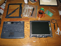
Display and base detached, display disassembled, and plug cut off from display.The connection was wired rather than being a flexible plastic circuit, so the decision was finally made to just wire in some other readily available connectors and use a readily available cable. The number of wires in the connection, the available space in the laptop display, and the stack of unused cables in my junk closet led to the choice... Parallel printer connectors. I cut off the plug from the display and was ready to go. 

Yes, it's backward.
Since a number of the wires were in twisted pairs, it seemed prudent to to use associated lines in the cable, if possible. Some searching turned up a table with complete parallel port cable pin assignments (see pp.9-10) and a connector pinout diagram with numbers adjacent pins for easy reference. Selecting one of the pins associated with a different signal ground pin for each of the twisted pairs and other pins for the remaining individual wires, the pinout was marked up according to the wire colors.

Then I noticed my mistake... The connections needed to be made to the female connector rather than to the male connector shown in the pinout diagram. Fortunately, this was a minor bump in the road. A couple of mild oaths and a bit of image processing later, I had an inverted image from which to work. Careful soldering to make the actual connections finished the initial work at the display end.

While it felt good to complete this first bit, a worry hung over the project... Would transmission line effects over a six-foot (182-cm) cable muck up the display? Would I need to put in extra impedance matching circuits? Instead of doing the wise thing and calculating it out, which would've required recalling forgotten college stuff from way back before the turn of the century, I had already decided to just try it. But I'd have to wait until the base connection was complete before seeing what would happen...